Petron Pason Mud Monitoring System – Used
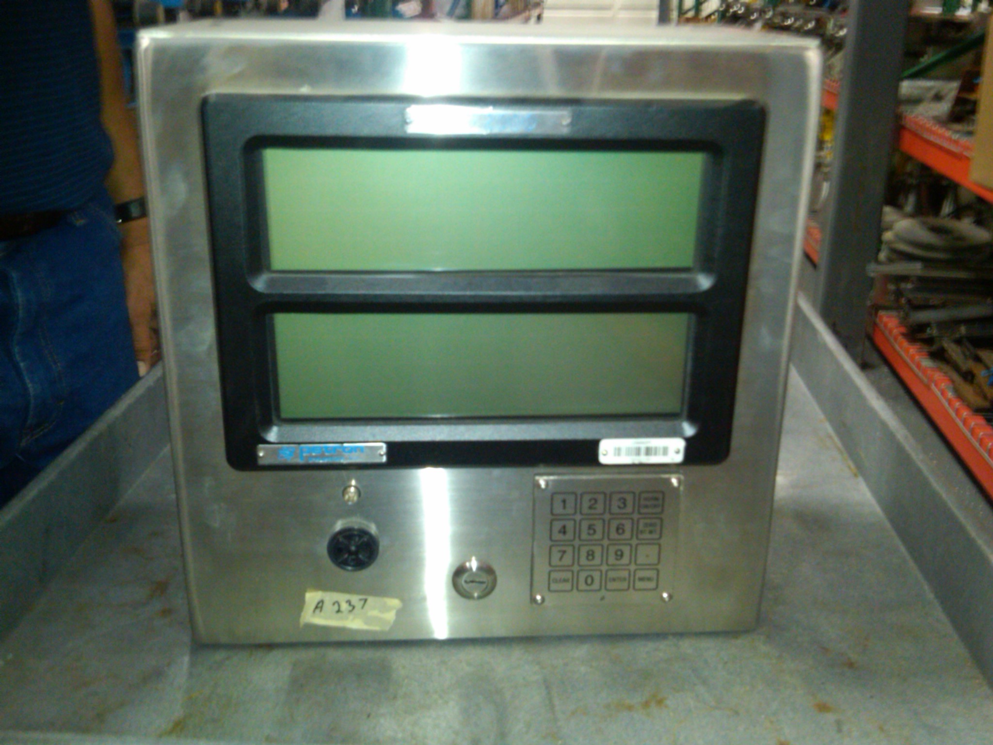
1ea. IDS 2000 Main Driller’s Display Console and Electronics (P/N A000237)
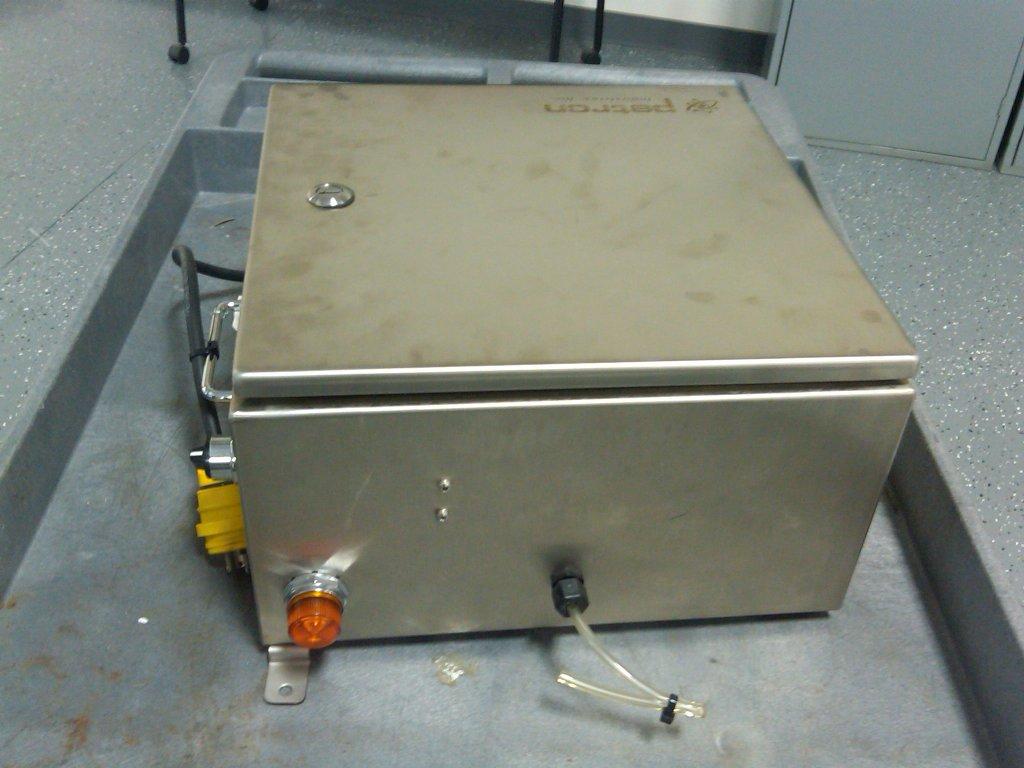
The IDS 2000 is designed for the rig floor environment. Featuring the same stainless steel display unit/junction box as the Petron Mud Data and Dril Data monitors, it can be surface or yoke mounted. Compact size and comprehensive functions make it ideal for rig retrofits, for new generation slim hole rigs, for advanced technology workover rigs, and coil tubing units. With the purchase of specific sensors, the IDS 2000 monitor tracks and records a wide array of drilling parameters such as rotary RPM, top drive RPM, standpipe/pump pressure, annulus pressure, depth/ROP/pipe velocity, hookload/WOB, rotary torque, and top drive torque. Monitored fluid parameters include mud pit levels (up to 8 pits), pump strokes, mud flow, fill strokes, mud weight, and mud temperature. It can also monitor mud gas measurement information with Petron’s optional hydrocarbon gas detector. The IDS monitor incorporates three types of operator screens and a security setup screen/menu. All screens have 8 lines of information. The three screens are: 1) DRILLING SCREEN: depth, ROP, hookload/WOB, standpipe/pump pressure, casing pressure, rotary RPM, torque, and hydrocarbon gas in the flow returns. 2) OFF BOTTOM/CIRCULATION SCREEN: When the bit is picked up off bottom, this screen automatically displays valuable off-bottom data: bit location; peak hookload; peak pipe velocity. This information, together with all other data displayed on the screen, is indispensable for early detection of hole difficulties and is invaluable in the control of potentially damaging surge/swab pressures and other related problems. 3) TRIP/PIT SCREEN: Selected by the driller immediately prior to making a trip, this screen displays vital trip parameters: bit location; hookload; peak hookload; pipe velocity; peak pipe velocity per pull; hole fill up (choice of pump or trip tank); accurate PVT and trip tank measurements. Includes isolation barrier to tie into top drive for rotary and RPM signal.
1ea. Depth Relay Module Included
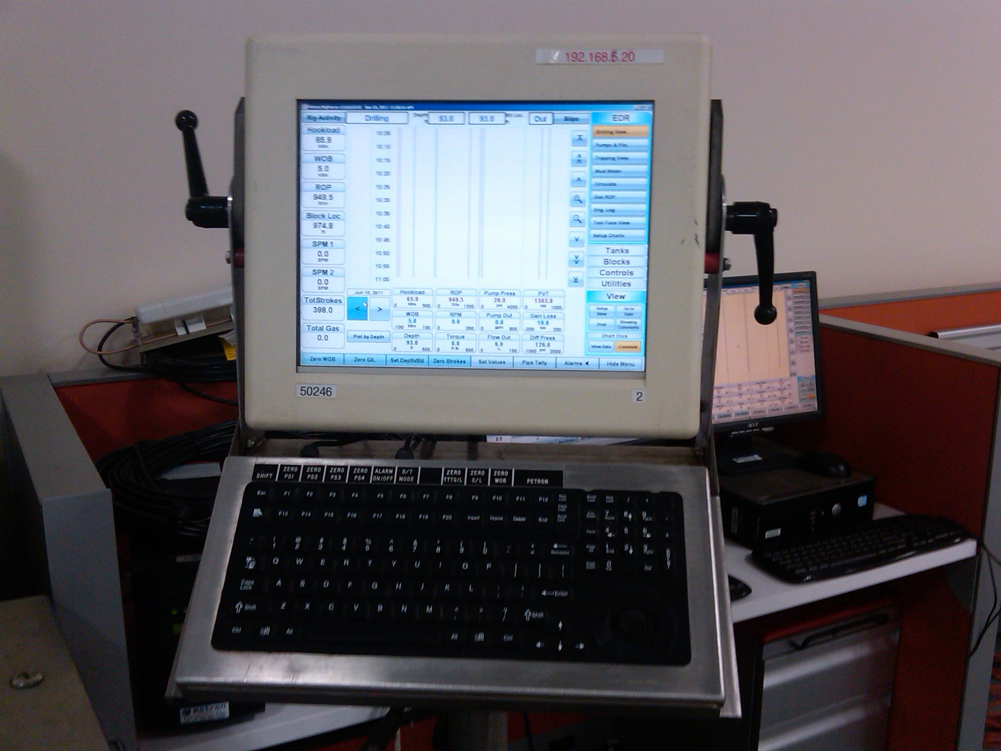
1ea. Driller’s Touch Screen Display & System Controller (P/N A000794)
The electronic hardware is a 15-inch LCD color flat-panel with touch screen and integral high
performance computer. The computerized display panel utilizes both RS-485 and Ethernet connectivity
to exchange data with the Petron system. In addition to the touch screen system navigation, the
capability to use an auxiliary keyboard and pointing device are available with this design. These panels
are housed in a Class I Div II environmentally sealed enclosure.
A special version of Rig Focus/Rig Brain software powers the system. This version is optimized for
Use on the drill floor with touch screen navigated computers.
1ea. Class I Div II Keyboard and Pointing Device for Touch Screen Display (P/N A000879) Included with Touch Screen
1ea. Uninterruptible Power Supply (P/N P003086)
1ea. J-Box for Communications (P/N A000811)
This includes fiber optic to 485 and fiber optic to Ethernet modules rated for Class 1 Div 2 area. Also includes 24V power supply to power the touch screen display
1ea. Y Type Purge (P/N A000593) Required for Class I Div 2 area.
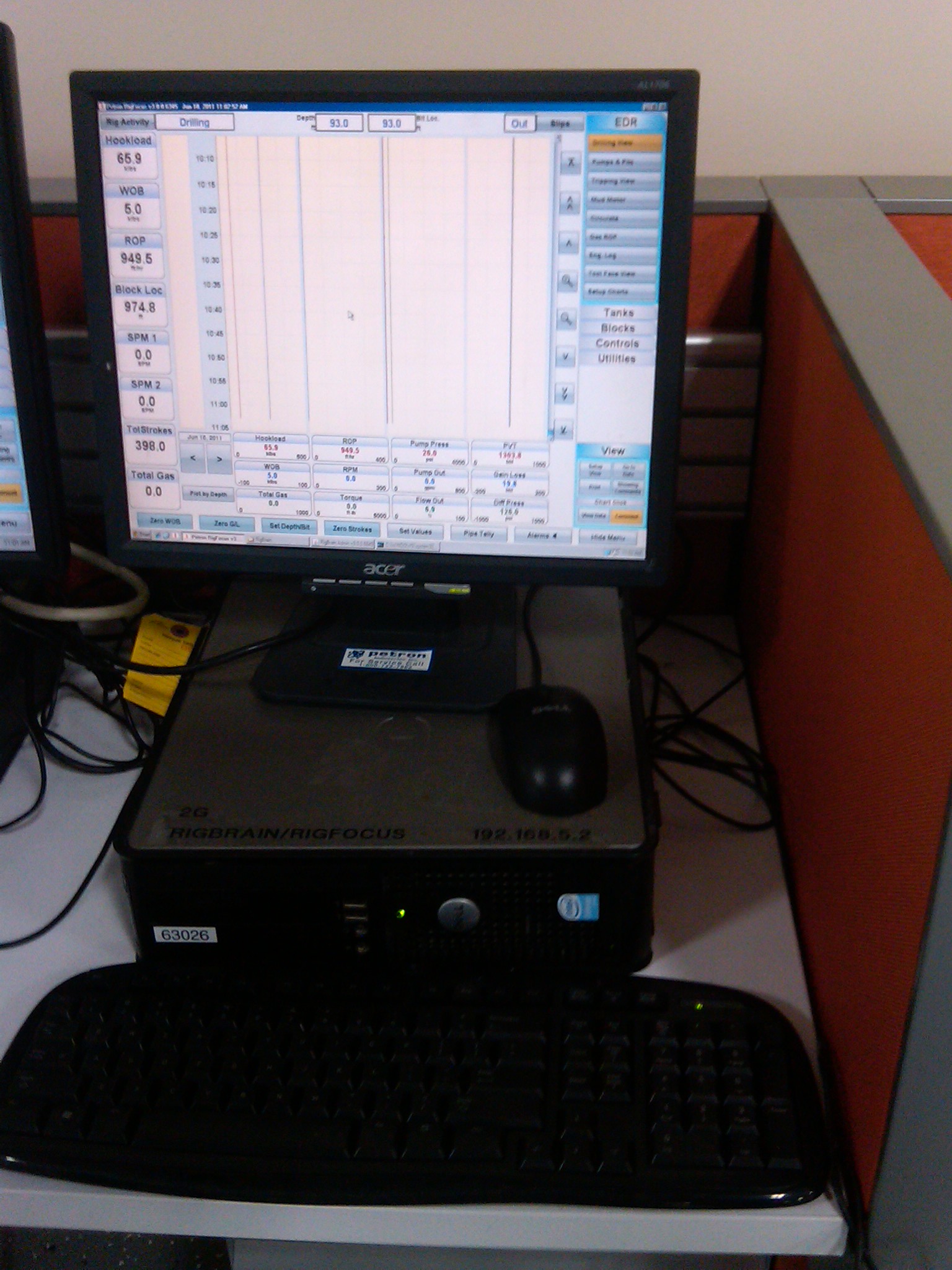
1ea. Petron Rig Site Workstation (Rig Focus/Rig Brain Software)(P/N A000924 computer; P002970 monitor; P001415 keyboard; P002514 mouse)
Software:
RigFocus™/RigBrain™ Workstation Version Features:
• Flexible real–time numeric data display capabilities.
• Audible and visual alarm capabilities.
• Precise time and depth based data charting.
• Flexible graphical tank display.
• Pre–configured displays available for quick and easy first time experience.
• Each user can easily setup any number of named display configurations.
• The chart configuration process is easy, flexible and includes setting up time or depth, tracks, traces, vertical and horizontal scales, and background color.
• Configurations and settings are saved on the server so they follow the user from computer to computer.
• Flexible printing options allow setting choices for tracks, traces, colors, and resolutions.
• A data popup window tracks the user’s mouse pointer to quickly access and browse numerical well data detail.
• Data File Export: LAS and CSV (comma separated values) in time and depth–based format.
• Integrated pipe and casing tally.
2ea. Wireless Ethernet Communications Box
1ea. Uninterruptible Power Supply (P/N P003086)
1ea. Printer (P/N P001609)
SENSORS:
5ea. Pit Volume Sensors – Radar (P/N A000756)
This type of sensor uses radar technology in either C (6GHz) or K (26GHz) band to continuously monitor levels of mud in the tanks. It is designed to omit any foaming or steam that can be generated by heat of the mud in the tank. It has a short antenna which emits short pulses. These pulses are reflected back and are received as echoes. It outputs a 4-20mA signal which makes it intrinsically safe. The calibration of the senor is accomplished using a handheld device which uses HART technology which is included
with the sensor.
1ea. Radar Trip Tank Sensor
1ea. Radar PVT Calibration Kit (P/N K000042) Included
3ea. Pump Strokes (proximity type) (P/N A000899)
1ea. Hook Load/WOB (Hydraulic hookload) (P/N A000113)
1ea. Depth/ROP/Bit Tracking/Pipe Velocity (P/N A000945)
Depth/ROP/Bit Tracking/Pipe Velocity: A series of targets adhered to the fast sheave, which are counted by a proximity sensor. This action calculates depth and rate of penetration, bit location, and peak velocity.
1ea. Pump Pressure (Hydraulic) (P/N A000260)
1ea. Rotary RPM
1ea. Rotary Torque
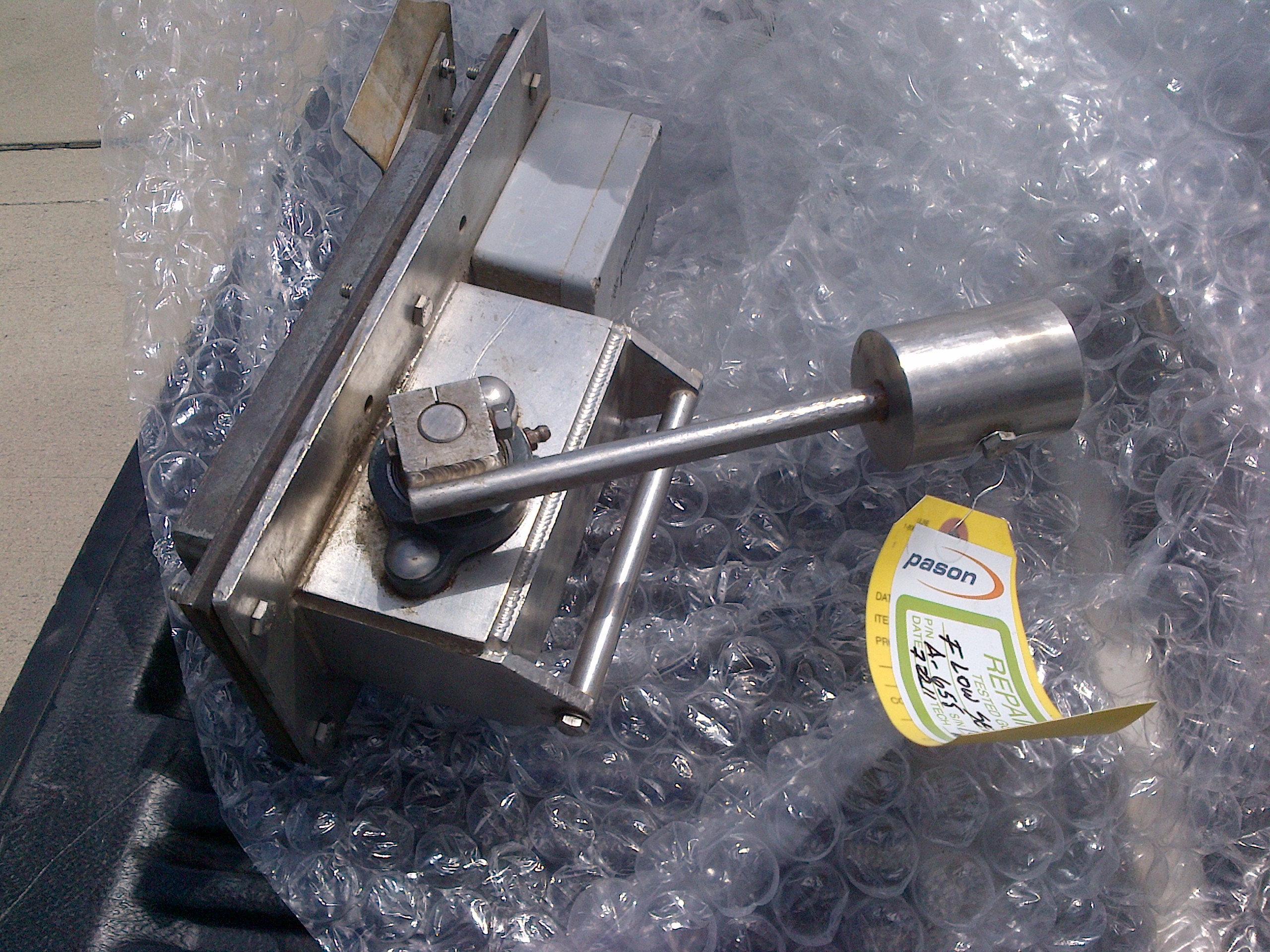
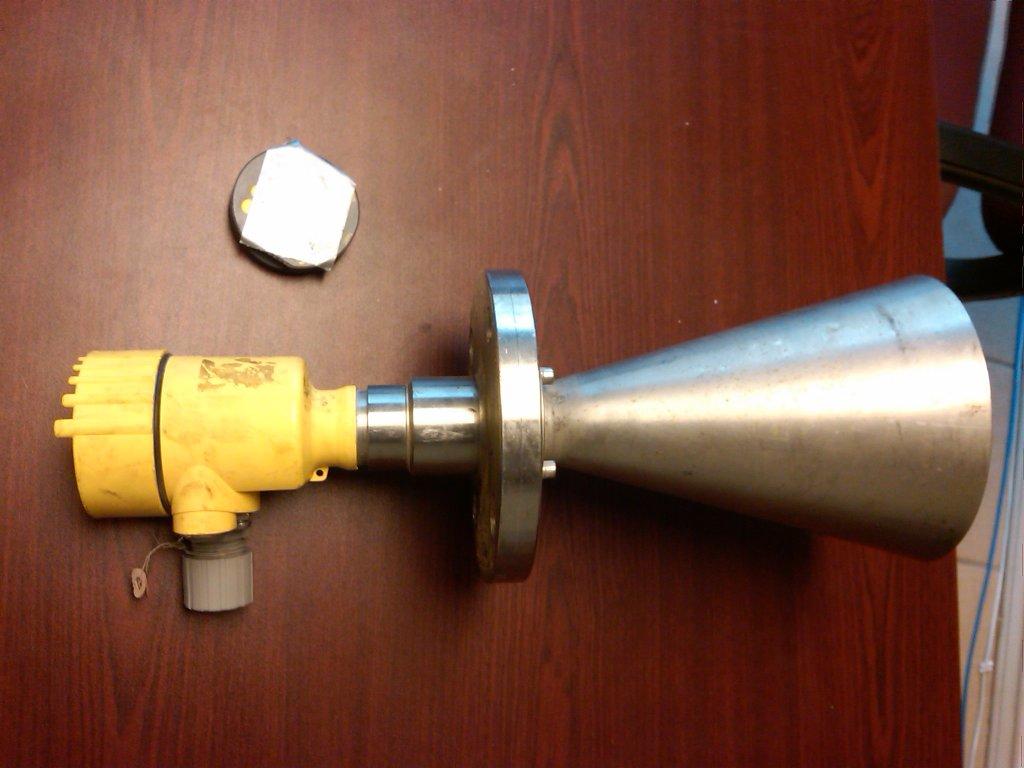
1ea. Flow Out Sensor (P/N A000655)
Flow sensor: Consists of a paddle assembly, which is inserted and attached to the flowline of the rig. The paddle is activated by the returning flow of mud. As the return flow raises the paddle, the shaft to which the paddle is attached also turns. On this shaft is mounted an asymmetrical cam, and as the cam is turned, the distance between the cam and the proximity sensor mounted on the housing is measured and converted into a signal which can be calibrated for the full length of travel of the paddle. Also mounted on this shaft is a counterweight which serves to bring the paddle back to a vertical position when there is no flow in the flowline, as well as provide resistance to flow in order to stabilize the action of the paddle. This entire assembly is attached to the flowline by utilizing a saddle made of angle iron, which is welded over the opening in the flowline through which the paddle is inserted.
1ea. Total Gas Detector with Gas Trap and Oiler/Regulator (P/N A000672 Gas Detector; A000589 Gas Trap; A000669 Oiler/Regulator)
The Total Gas Detector continuously measures total hydrocarbon gas levels. An automatic scale change and dilution system prevents over-ranging and ensures continuous operation without manual control. Internal automatic zeroing compensates for detector aging and temperature drift. The detector element is an especially durable and stable platinum/palladium coated ceramic bead. Normal calibration of the instrument is 100 gas units for 1% mixture of methane in air. Gas mixtures up to 100% concentration can be monitored.
Power and Signal Outputs Specifications:
Power: 110 VAC, 60 HZ, 2 ½ amps
Gas Trap for Total Hydrocarbon Gas Detector – Constant flow degasser, designed and built (stainless steel) to ensure that within reasonable variations in the mud level in the header (shaker) tank, the gas trap pumps a constant volume of mud through itself per unit time, thus ensuring the most representative and accurate gas reading. The trap is intrinsically safe using an air motor to drive the pump, and the device is adjustable for different mud levels.
Click HERE to view the inventory (Adobe PDF 206kB)